- Your gateway to the Maritime Knowledge!
- [email protected]
Mooring Winch Brake Testing on ships

Rudder Cycling
March 30, 2020Introduction
Mooring winch brake testing on ships is one of the most crucial test carried out onboard. Winches are one of the most critical equipment on board ships. It is needless to emphasize upon the fact that how important it is to keep a check on the performance of your winches.
Erratic performance of the winches have lead to many disasters and casualties on board ships in the past.
An important performance criteria of any winch is its Brake. And so is mooring winch brake testing.
Brake is one of the most important feature of a winch. It ensures that the winch holds drum (and consequently the mooring rope) in its position so that the moorings are kept sufficiently tight. Another important function of the brake is called ‘rendering’ which ensures that the mooring line shed its load before it parts (through slipping of drum), just in case it undergoes excessive stress. This is called Brake Rendering. We will discuss how to carry out mooring winch brake testing but before that let us learn few important concepts.
What is Brake Rendering?
To state simply, the “slipping of brake ” resulting in release of load or stress on the tightened mooring line , before the mooring rope on it reaches its MBL (Minimum Breaking Load) is called Brake Rendering. Brake Rendering of a winch ensures that the line (which due to some reason is under excessive stress), gets paid out before it reaches it MBL or Minimum breaking load.
Before we move further, it is prudent to know the meaning of Brake Holding Capacity.
What is Brake Holding Capacity ?
It is the Maximum Capacity of the mooring winch brake to hold the mooring drum in its position when under tension. Technically, Brake Holding Capacity of a winch is 80% of the MBL of the Mooring Rope, but it is set at 60% of the MBL, allowing 20% margin for safety (OCIMF guidelines).
Above this figure (of 60%), the brake renders.
So, in a nutshell, the Brake holding Capacity of a winch is required to be 80% of the MBL of the rope (this applies to new ships). Keeping 20% of the MBL as the safety margin, the holding capacity is required to be set at 60% of the MBL (OCIMF Guidelines)
According to this, when the winch drum is subjected to the load in excess of 60% of the MBL, the brake should render.
I hope that above is clear.
Lets move ahead.
Brake Rendering Test
To determine the Brake Rendering Capacity of the Winch, a procedure called Brake testing is carried out. This procedure requires a Brake Testing Kit which has the following components –
1. Hydraulic Jack with Manometer and lifting arrangements and base support (if required)
2. Plates
3. Bolts to fasten the plates to the winch drum
The break testing kit simulates the load on the line by means of hydraulic pressure producing a torque on the winch drum as shown in the figure below-
Principle
For Example, we have a mooring hawser with Breaking Load of 451kN. Now, 80% of 451kN is 360.8kN or simply 361kN. Note that Area of Hydraulic Jack being used is 0.1450 m2.
I have obtained this data from my previous vessel.
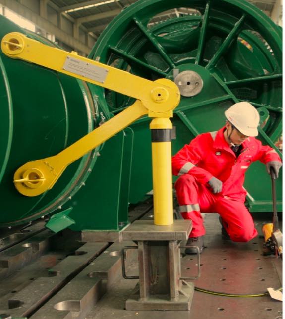
So let us test the Brake Rendering capacity of the winch shown below –
In the above figure, pay attention to the rigging of brake testing equipment. Special attention shall be paid to the Position of the Hydraulic Jack and connection of Triangular plate WITH RESPECT TO the payout direction. Please give this a good attention as rigging it incorrectly may damage the equipment or winch or both.
Now, Remember the following –
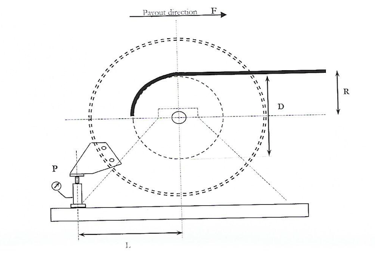
Brake Rendering Force = (F X L) / R
(At 1st Layer in kN)
Where L= Distance of Drum Centre from the Hydraulic Jack
R=Distance of Drum Centre from the First Rope Layer [(D1+D)/2]
Where D1= Diameter of the Rope (cm)
D= Diameter of the Drum (cm)
F= Force applied by Hydraulic Jack [ P(Mpa) x 10 x 0.145]
Where P =Hydraulic Jack Pressure at Brake Render Load
L needs to be measured physically
D can be obtained from the winch manual , D1 from the Rope certificate
P is read off by the pressure gauge (manometer) fitted on/with the Hydraulic Jack.
Procedure
-
Rig the Brake testing kit as shown in the figure above. Manufacturers instruction should always be consulted prior such test
-
Jack shall be placed firmly on the ground and in correct position
-
Ensure that pressure gauge on the hydraulic jack showing zero
-
Tighten the brake of the mooring winch fully
-
Now we know from calculations that the brake of the winch shall be so adjusted that it will render at a load just above 361kN say 362kN.
If you are clear till this point, you are doing a very good job!
Lets continue then –
6. Start pressurizing the jack so that it starts to create a torque which acts in the direction of the lower as shown above (this simply means we are trying to make the brake ‘slip’ or render)
7. From the above formula, we can simply determine that the force required to be applied by the Hydraulic Jack needs to be about 104.5 MPa which is corresponding to the Brake Rendering Force of 362 kN (Just above 361kN)
In other words, if we want the Brakes to render just above a force of 361kN then we need to pressurize our jack to 104.5 MPa
8. Pressurize the jack to a pressure of 104.5 MPa and hold.
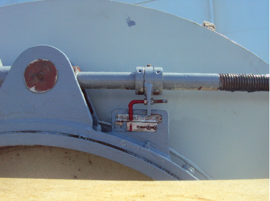
9. A marking is required to be made on the brake screw indicating the limit to which it should be tightened.
10. This position is held for a minute and the marking is checked again to see if there is any slip.
11. The same procedure is followed for other winches and result tabulated as shown below –
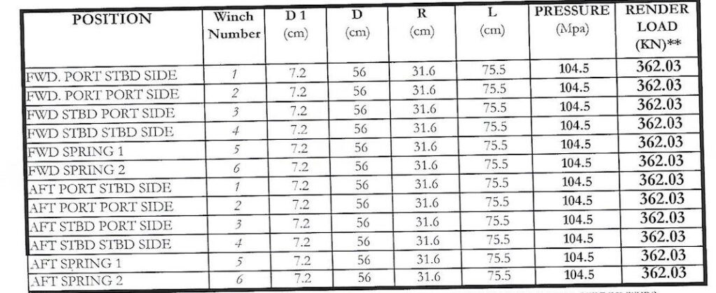
This completes the Brake Rendering Test procedure.
Do note that the effectiveness of the Brake Holding will be determined by the condition of the brake lining. Comply with Manufacturers instructions carefully in order to ensure that brake holds and render at the correct load. You can also read this article here for more clarity on the topic.
Do share your thoughts & suggestions in the comment section below.
Fair Seas & Bonn Voyage!


2 Comments
[…] Only the rope with proper specifications (intended to use for a particular purpose) shall be ordered. Particular attention shall be given to the size, material and SWL of the rope. On one instance, wrong Mooring hawsers were ordered – SWL of which was not in line with the Brake rendering capacity of the Mooring Winches in use! For more clarity you can read the topic on Mooring Winch Brake testing procedure on ships here. […]
Mooring Winch brake testing procedure.